

close
Choose Your Site
Global
Social Media
Author: Site Editor Publish Time: 2026-10-31 Origin: Site


Ever fried an expensive audio system? For system integrators and AV installers, a mismatched setup is an absolute nightmare. It means blown transducers. It means smoking hardware. Worst of all, it means costly return visits to face unhappy clients. Navigating the technical jargon of ohms, watts, RMS, and peak power can be overwhelming. This is especially true when you are trying to pair complex multi-zone arrays with commercial racks.
This comprehensive guide breaks down exactly how to achieve perfect loudspeaker system matching. By understanding these core electrical principles, you ensure your installations remain safe. They will deliver pristine sound and last for years without thermal failure. Before diving into complex wiring diagrams and series-parallel math, let us establish the foundational rules of electrical acoustics.
To design a reliable architecture, you must first grasp how electrical signals travel from a power source to a driver. The relationship between wattage and resistance forms the baseline of all acoustic engineering.
In the context of AV integration, power is the electrical energy pushed to the voice coil to create sound. However, not all ratings on a spec sheet are created equal. This often misleads novice installers.
The critical distinction lies between RMS and Peak Power. RMS represents the true, sustained energy a unit can deliver over an extended period without overheating. In contrast, peak power refers to instantaneous, split-second bursts during loud transients. Think of a sudden snare drum hit. For professional system integration, you should strictly use the RMS rating for your calculations. Relying on peak numbers is a guaranteed recipe for a severely underpowered and distorted rig.
Impedance, measured in Ohms, is the electrical resistance applied against the output current. Because audio signals utilize alternating current, this resistance actively fluctuates with frequency. For calculation purposes, manufacturers provide a nominal rating. This is typically 4, 8, or 16 ohms.
Consider a standard water pipe analogy to visualize this. Voltage acts as the water pressure. The amp is the water pump. Impedance represents the width of the pipe. A lower impedance acts like a wider pipe, allowing more current to flow freely. While this yields higher volume, it forces the pump to work significantly harder. If the pipe is too wide, the pump will eventually burn out from overexertion.
Achieving rock-solid stability in commercial environments requires more than just plugging bare wire into binding posts. It demands a rigorous mathematical approach to electrical loads.
Precise matching ensures maximum energy transfer and long-term hardware survival. When the electrical load perfectly aligns with the output capabilities of the rack, the entire chain operates at peak efficiency.
Furthermore, it is vital to recognize that resistance is highly dynamic. An 8-ohm rated driver does not measure exactly 8 ohms during playback. Due to inherent impedance curves, the resistance shifts based on the frequencies being reproduced. A subwoofer might dip to a grueling 3 ohms during a heavy bass drop while peaking at 20 ohms in the upper registers. This dynamic environment is exactly why deploying a stable, high-current professional power amplifier is absolutely essential. If the unit cannot handle sudden dips in resistance, it will trigger thermal protection and abruptly mute the zone.
Analyzing recent industry shifts reveals a massive transition in commercial AV design. Modern system integration is rapidly moving away from purely analog guesswork. Today, high-end commercial installations increasingly rely on DSP-driven architectures featuring active impedance monitoring. Installers are demanding hardware that goes beyond standard thermal limits. Instead of simply blowing a fuse when a load drops too low, modern smart amplifiers analyze the impedance curve in real-time. They automatically limit current output or alert the integrator via network software before catastrophic failure occurs. This trend underscores a crucial reality. Integrators must move beyond matching basic numbers on paper. They need to utilize intelligent hardware that actively adapts to real-world acoustic anomalies.
Integrators must be adept at interpreting technical specification sheets. A typical professional unit might list its specs as 500W per channel at 8 Ohms and 750W per channel at 4 Ohms.
This matrix indicates the chassis is stable down to a 4-ohm floor. If you connect a single 8-ohm box, it delivers 500 watts of continuous power. Drop the resistance by connecting a 4-ohm box, and the unit pushes 750 watts. Mastering this matrix allows you to select the exact number of transducers per channel without exceeding thermal limits.
| Amplifier Rating | Speaker Load | Resulting Output | System Status |
|---|---|---|---|
| 500W @ 8Ω / 750W @ 4Ω | 8 Ohms | 500W Continuous | Optimal / Safe |
| 500W @ 8Ω / 750W @ 4Ω | 4 Ohms | 750W Continuous | Maximum Efficiency |
| 500W @ 8Ω / 750W @ 4Ω | 2 Ohms | N/A | Danger / Thermal Overload |
For rapid and reliable deployment in the field, seasoned engineers rely on established industry standards. Adhering to these two fundamental laws will virtually eliminate your hardware failure rates.
The golden standard dictates that your RMS power output should be 1.5 to 2 times the RMS power handling rating of the connected transducer. For instance, if you are mounting a ceiling speaker rated for 100W RMS, your rack should ideally provide 150W to 200W RMS at that specific ohm load.
Why is this buffer necessary? Providing headroom prevents the circuitry from ever needing to operate at maximum capacity. When pushed to its absolute limit, a unit runs out of voltage to reproduce the peaks of the audio waveform. This forcibly clips the tops off the sine waves, transforming them into harsh square waves. Square waves dump massive amounts of unnatural, continuous energy into the voice coil. This melts the internal glue and fries the driver almost instantly.
The second rule is absolute and unforgiving. Never connect a total load that is lower than the minimum rated impedance of your equipment. If the spec sheet clearly states a minimum load of 4 ohms, wiring a 2-ohm array will cause an immediate and dangerous overcurrent draw. This inevitably leads to blown internal fuses, melted output transistors, or a tripped breaker.
Despite best intentions, mistakes happen when sweating over a complex rack in a cramped AV closet. Understanding the physics behind these failures helps you troubleshoot issues rapidly.
Imagine connecting a 4-ohm speaker to an amp strictly rated for 8 ohms. This is the most dangerous scenario in our industry. Because the 4-ohm load offers too little resistance, it pulls significantly more current than the power supply was designed to generate. The chassis will quickly overheat. It will engage thermal protect mode or permanently short out.
Conversely, pairing an 8-ohm speaker with a 4-ohm stable amp is generally safe and will not damage your gear. The higher resistance restricts current flow, keeping temperatures low. The trade-off is efficiency. The system will output significantly less power. This usually equates to about half of its 4-ohm rating. Ultimately, you will not reach the maximum SPL potential of your design.
A pervasive myth among novice installers is that too much power blows speakers. In reality, a severely underpowered rig is far more lethal. When an integrator pairs a 50W amp with a 300W speaker and cranks the dial to achieve high volumes, the weak amp is pushed into severe clipping. This generates high-frequency harmonic distortion. It completely bypasses the internal crossover network, dumping raw energy directly into the delicate tweeters and destroying them.
When designing multi-zone commercial spaces, you rarely wire just one box per channel. Daisy-chaining multiple units across a large room requires strict mathematical calculations to maintain a safe electrical load. Proper loudspeaker system matching here prevents entire zones from going offline.
Parallel wiring is the most common technique used in the field. In this circuit, all positive terminals connect to the positive output. All negative terminals connect to the negative output.
To calculate identical speakers, simply divide the impedance of one unit by the total number of units. Two 8-ohm speakers in parallel create a 4-ohm total load. Integrators utilize this method to extract maximum wattage, as it lowers resistance and forces more current flow. Extreme caution is required. Adding four 8-ohm speakers drops the load to 2 ohms, which is fatal for most standard commercial gear.
Series wiring involves routing the negative terminal of the first unit to the positive terminal of the second. This creates a single continuous loop.
Here, the math is straightforward. You add the values together. Two 4-ohm speakers in series equal an 8-ohm total load. This defensive strategy is used to raise the overall resistance. It protects the rack from dropping below its minimum threshold. The downside is that if one voice coil blows, the entire chain breaks, silencing the whole zone.
For large arrays, such as hanging eight pendants on a single channel, professionals use series-parallel combinations. By wiring two pairs of 8-ohm speakers in series, you create two 16-ohm loads. Then, by wiring those two pairs in parallel, the total system impedance returns to a perfect 8-ohm load. This clever math allows you to run large arrays safely without melting your hardware.
The physical scale of the venue dictates your matching methodology. You must evaluate cable lengths and zone sizes before deciding between traditional setups and constant voltage architectures.
Standard low-impedance matching is strictly reserved for high-fidelity, high-impact, and short-distance applications. Because these signals suffer from heavy degradation and power loss over long wire runs, this architecture has limitations. It is ideal for nightclubs, live concert stages, recording studios, and premium home theaters where the rack is relatively close to the drivers.
For sprawling environments like international airports, shopping malls, and corporate office buildings, traditional ohm-math becomes obsolete. Running hundreds of feet of copper wire introduces massive cable resistance, ruining audio quality.
Specifically, this is where 70V and 100V constant voltage systems shine. By using step-up transformers at the rack and step-down transformers at each speaker, you bypass traditional impedance calculations entirely. Instead, you simply match total wattage. If you have a 500W 70V amp, you can safely daisy-chain forty 10W ceiling speakers in parallel. This leaves a 100W safety buffer. This high-voltage, low-current approach is mandatory for massive, multi-zone commercial integrations.
With the math and physics established, the final step is hardware procurement. Selecting the right unit requires evaluating internal topologies and crucial feature sets tailored for B2B installations.
The internal circuitry dictates efficiency, weight, and thermal output. Traditionally, Class AB was the standard, known for warm and accurate reproduction. However, they are incredibly heavy and dissipate massive amounts of wasted energy as heat. This requires extensive rack cooling.
Today, Class D is the undisputed king of commercial integration. Utilizing pulse-width modulation, Class D units achieve over 90 percent electrical efficiency. They run exceptionally cool, are lightweight, and can deliver staggering amounts of power in compact 1U or 2U spaces. This makes them perfect for crowded AV closets.
A basic power block is no longer sufficient for complex jobs. You should prioritize equipment featuring built-in DSP. Onboard digital signal processing allows for precise crossover manipulation, room EQ tuning, and time alignment. Most importantly, integrated peak limiters and active thermal monitoring are mandatory. They protect your investment from unauthorized users cranking the volume knob.
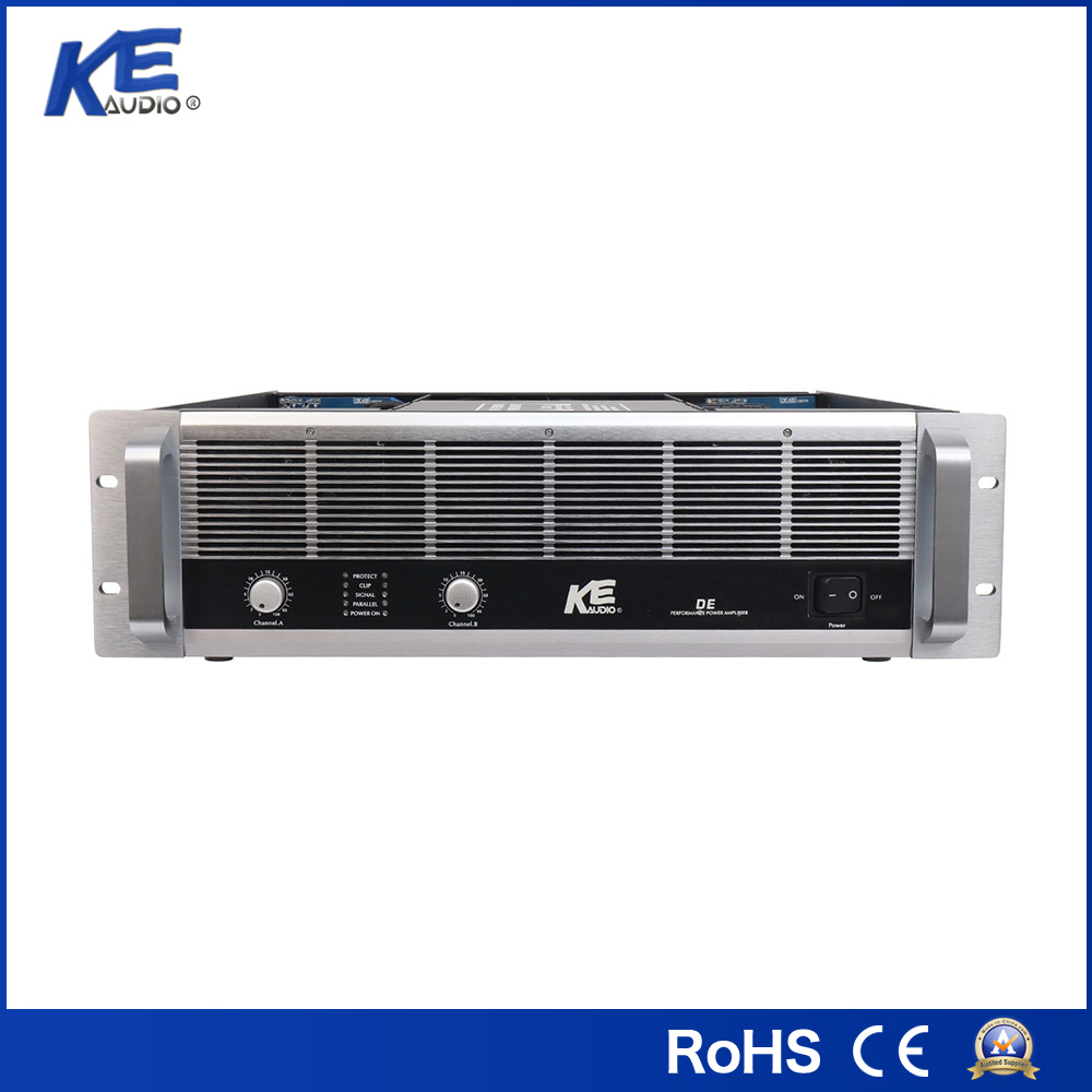
To streamline procurement and guarantee compatibility, partnering with a reliable manufacturer is critical. Selecting a high-performance professional power amplifier ensures your system possesses the necessary thermal stability and RMS headroom required for demanding environments. Look for series that offer robust two-channel configurations, comprehensive DSP controls, and stable 4-ohm operational floors.
The longevity of any commercial audio installation relies heavily on respecting the laws of physics. Always ensure your total electrical load is equal to or higher than your minimum rating. Meticulously provide adequate RMS headroom to prevent destructive clipping. Taking the time to calculate parallel and series loads before stripping a single wire saves money. It prevents catastrophic equipment failure and guarantees absolute client satisfaction. For your next large-scale deployment, explore the full range of audio solutions at KE Audio to find the perfect match for your commercial requirements.
Yes, provided the speaker's resistance is higher than the minimum rating of the unit. For example, connecting an 8-ohm driver to a 4-ohm stable channel is perfectly safe, though it will output slightly less volume. Conversely, connecting a lower impedance load to a higher-rated channel will cause severe overheating and permanent hardware damage.
It is strictly better to have a higher wattage power source. Industry standards dictate providing 1.5 to 2 times the RMS capability of the transducers. This ensures the delivery of clean, undistorted transients. A weak unit pushed to its absolute limits will generate clipped, square-wave distortion that quickly melts voice coils.
A standard compatibility matrix maps the continuous output wattage at specific ohm loads against the RMS handling and nominal resistance of the drivers. The intersecting points clearly highlight safe zones with adequate headroom, underpowered risks of clipping, and danger zones of electrical mismatch.
Mixing different impedance ratings on a single channel is highly discouraged. The mismatched drivers will draw current unevenly, resulting in drastically different volume levels across the room. If absolutely unavoidable, you must carefully calculate the total parallel or series load to ensure the combined resistance does not drop below the minimum safe operating threshold.
While excess power is generally safer than underpowering, extreme mismatches can still cause mechanical failure. If you push 1000W into a 100W speaker, the voice coil will over-excurse and physically tear. However, properly setting DSP limiters and maintaining responsible volume levels allows a high-powered unit to drive smaller speakers effortlessly and cleanly.
Subwoofers demand massive current due to their large voice coils and heavy bass frequencies. You must ensure the amplifier can handle intense impedance dips, often dropping below 4 ohms during heavy transients. Always match the RMS power, and consider bridging two channels into a mono block to provide the necessary headroom for tight, distortion-free low-end reproduction.


